

The North American Aviation (NAA) G5B gyroscope was last in a series of gyroscopes that used ball bearings to support the rotor. It was considered an obsolescent design in that the practical limits of ball bearing technology, as applied to gyroscope rotors, had been reached. The basic design of the component parts of the gyroscope have stayed the same for many years – they may be in use today. However, the future of NAA gyroscopes was through the development of low friction gas bearings for gyroscope rotors. The G5B was the gyroscope chosen for the N5 Inertial Navigation System (INS) and the N5 INS was selected for use on the NAA Hound Dog cruise missile.
The G5B was a single degree of freedom type gyroscope, ie, it controlled one axis. The gyroscope consisted of a case assembly and a gyroscopic assembly. The case assembly was fixed in position to the INS stable platform and it fully contained the spherical shaped gyroscopic assembly in a spherical chamber. Movement of the spherical gyroscopic assembly, (the float), relative to the case assembly, (the case), was constrained by two fluid bearings spaced 180 degrees apart. The two journals of the fluid bearings were fixed to the float. The fluid bearing defined the axis of the angular movement of the float relative to the case and constrained lateral movement of the float relative to the case. The space between the case and the float was filled with a fluid of such density that the float was neutrally buoyant.
What follows are descriptions of the major subassemblies of the gyroscope and the function of each. These are based on my recollection of the details of my work experience and today’s speculation. As such, they are to be taken as gospel at your own risk.
a.) Pump
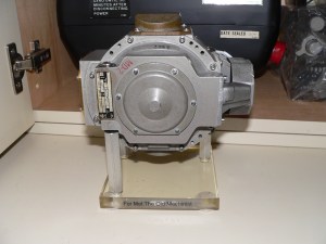
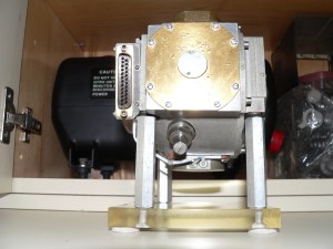
An electromagnetic pump, utilizing a solenoid driven piston, provided the fluid pressure and flow necessary for the fluid bearing to operate satisfactorily. The pump is shown in IMAGE ONE. It is the darker gray assembly in the far right. The pump is also seen in IMAGE THREE.
b.) Pickoff
The pickoff provided a signal proportional to the angle between the case and the float. The pickoff consists of a flat coil, shaped as a paddle, which is fixed to the float. An excitation coil assembly is fixed to the case. A current proportional to the float angle is inductively produced in the “paddle coil”. Zero current significates zero float angle and the phase of the current determines the polarity of the float angle. The pickoff protective cover is shown at the top of IMAGE ONE. It is “gold” colored in the image.
c,) Float Stop
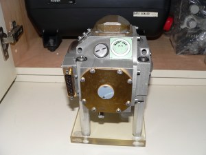
A “hard and soft” stop device is provided to limit the angular rotation of the float. It is important to avoid damaging any float appendages by allowing rotation of the float to the extreme limit. As the float nears the maximum rotation allowed, a pin fixed to the float first contacts a cantilevered flexible spring fixed to the case. Continued float rotation is inhibited by the continuation of the bending of the cantilevered spring (the “soft” part), until the hard limit is reached. The stop travel limit adjustment screw is shown in IMAGE TWO. It is the set of three screws shown just below the gold colored pickoff cover.
d.) Torquer
It is necessary, for both system use and laboratory testing of the gyroscope, to provide a way to apply a calibrated torque to the float in order to cause the gyroscope to precess at a known rate. A “voice coil” type device was used to produce the force (the torquer). This force, acting through the radius of the float, resulted in the precession of the gyroscope rotor. The mechanization of the N5 INS was such that the INS stable platform remained at local level at all times. This requirement that the stable platform be kept locally level meant as the INS moved over the Earth’s surface, each gyroscope of the INS must be caused to precess thru the appropriate angle to maintain the stable platform at local level. The force was generated by causing a calibrated current (the torquer current) to flow in the “voice coil” attached to the float. The magnetic field thus created interacted with the magnetic field produced by a constant current (the field current) flowing in “field coils” attached to the case and, thru this interaction, produced the desired force. The torquer is thought to be beneath the gold colored cover seen opposite the pump in IMAGE FOUR.
e.) Flex Wires
The float moves with respect to the case but power and signals must cross between them. The substantial number of wires needed and the wire stiffness make it impractical to wire directly to the float. The wires instead went to a circular array of standoffs arranged symmetrically around the case axis. The float wires went to a similar set of standoffs mounted on the float. A flexible “krinkle wire” was attached to each standoff pair. The “krinkle wires” allowed the power and signals to cross the gap without placing undue drag limitations on the rotation of the float. It is thought the flex wire assembly is under the gold cover seen in IMAGE FOUR.
f.) Bellows Assembly
A bellows assembly was provided to accommodate the change in fluid volume that results from temperature changes of the gyroscope. The location of the bellows assembly is not known, but is under one of the cover plates observed on the outside of the gyrosope.
G.) Fluid Fill Port
The fluid fill port is seen in IMAGE FIVE.
Thank you Tony for your permission to use the images in this Blog.


Mel,
Thank you so much for the technical description of the G5B gyro, beautifully done. What rpm did the rotor spin at? In your previous description of the N5 platform you mention 6 gyros where used. How heavy was the N5 platform? I’m guessing my gyro is about 5 lbs., 6 gyros plus gimbaled platform must of been over 100 lbs.? holy moly!
I have more questions for you but I need to do further research.
Tony
I am looking for a photo of an early NAA gyro that could be used as part of an NAA Memorial/Historical display at the Downey, CA Science Museum. Maybe a photo of the internal components, instead of just a housing? Thanks for your help.